• X-Ray

    Gradients and X-ray tubes

    Fusion imaging is a method full of surprise. My red calla lilies revealed an effect I had forgotten completely. There must be a gradient in every X-ray exposure.

    Preparing a fusion image composition with my 6 red calla lilies I found a troublesome gradient in the X-ray. 

    Gradient in an X-ray of 6 red calla lilies © Julian Köpke

    The cause for the gradient is a weakening of X-ray radiation at its origin in the X-ray tube. A closer look at the phenomenon can be found in my FAQ. This effect of variable recording of photons phycisists call „anode heel effect“.

    As part of my creative process I rotated the composition shown above by 180 degrees and exposed it a second time with the same parameters. Note that post-production as well was done equally for both X-ray exposures !

    Gradient in an X-ray of 6 red calla lilies, inverted for creative reasons © Julian Köpke
  • FAQ: Gradients

    It has been a long time since I thought about the basic properties of X-Ray tubes in graduate school. But I stumbled over an effect the other day that reminded me of one of these properties while using my new digital x-ray system. When I looked at this x-ray capture of six calla lilies, it was immediately clear that the system had operated in a way I had not entirely expected.

    The background of the calla lily x-ray shows a gradient of deep black values at the top of the image ranging to intermediate gray values at the bottom. This was surprising. 

    At first I suspected a problem caused by the sensor. But after a little reflection, I realized this was not the case. It was not a bug, it was a feature !

    Darker values in an X-ray film exhibit higher intensities of X-ray photons. Lower gray values mean lower intensities. Reading a bit more thoroughly about properties of X-rays and their production, the reason for the phenomenon became apparent to me. As the image of calla lilies shown above demonstrates, the distribution of X-rays emerging of a X-ray tube is not homogenous.

    X-rays are produced by accelerating electrons towards the anode of an X-ray tube. The anode is made of metal in the shape of a plate. The applied electric voltage to the anode is positive and the negative charged electrons fly therefore straight into the anode. A magnification of this process is shown on the following plan:

    Creation ox X-rays at the anode of an X-ray tube © Julian Köpke

    The path of the electrons is about 6 – 8 cm long. About 1% of the braking energy in return is transformed into X-rays. 99% is heat production in the anode. The most common construction type of X-ray tubes in the medical diagnostic field is therefore constructed with a very rapid spinning anode to expel the heat.

    The focal point on an anode is not a mathematical point. It is more like a circle (an even close model is an ellipse with a diameter of about 4 -5 mm). After electrons have entered the anode material and are slowed down, X-ray radiation leaves the edge of the plate. As the anode has an edge formed as an inclined plane, some X-ray photons can move freely, others have to pass a little more through the material of the anode. The longer the path of the photons through the anode is, the weaker the radiation’s intensity and the less is the sensor black. This effect of variable recording of photons by the anode plate is called „anode heel effect“. You can find more information on this topic in a Wikipedia article.

    The described gradient on an X-ray exposure can be used creatively. Before looking at these creative possibilities, note that it is easy to use post-production tools such as Photoshop to compensate for the gradient.  Medical diagnostic digital X-ray systems are already using something similar to compensate for the gradient.

    Using the gradient that is generated creatively means taking control of the process. For example, by rotating the composition shown above by 180 degrees and exposing it a second time you get soft contrast in the calla lily blossoms and a “hard” contrast in the rendition of the stalks (see image below). For comparison, in the medical field an appropriate exposure would use the higher X-ray photon intensity at the bottom for structures that are more dense on one side only (for example, the heel of the foot). Note that acquisition (x-ray exposure) and post-production were done equally for both X-ray exposures !

    Heel effect in X-ray photo of Calla lilies © Julian Köpke
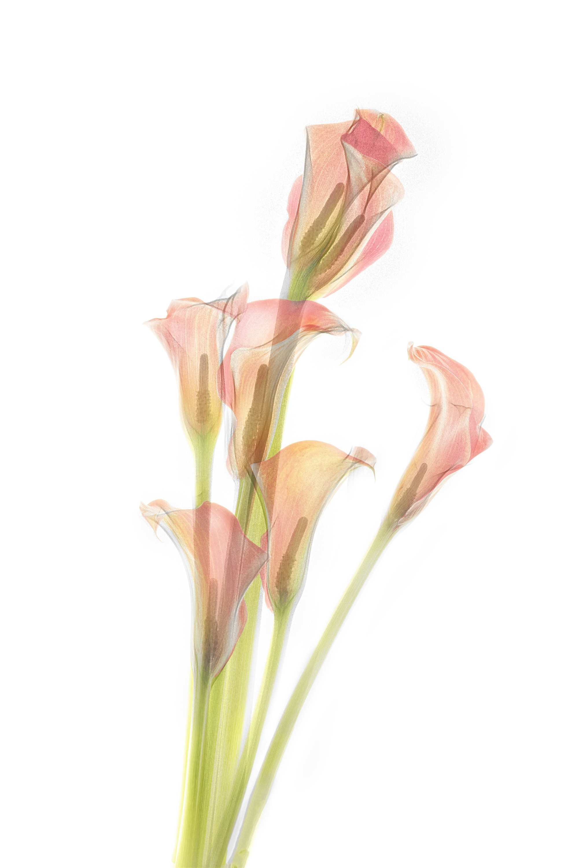
    Any rotational position can be thought of to integrate this effect in an image. The only limitation is the X-ray lighting area.

  • X-Ray

    Red calla lilies

    Sometimes reality falls behind our expectations. With 6 red calla lilies I felt well prepared to do some new X-rays and HDR images for image fusion. But my X-ray system surprisingly raised a barrier. The main computer stopped doing his job. 

    Many thoughts ran through my brain. Will we be able to examine patients the next day ? How fast the supplier will be able to react ? Will the company find a cause of this disturbance ? How many days will my calla lilies be alive ?

    I found a work-around by thinking over the interacting hardware. Doing some steps and with a newly restarted system I was able to create 7 different compositions without further disruption of which I show here No. 4.

    With X-rays emerges a more impressive illusion of transparency than a plain HDR would have been able to produce. Even when using a lightbox.

    Similar to a lightbox it produces better results when laying a petal or a complete blossom over the top of the stalk of another one.

    On top of the longest stalk is a twin blossom !

    Fusion X-ray photo Calla lilies IV © Julian Köpke

    You never know if the inversion in Lab colors leads to an attractive result. It’s always worth looking at Lab color transformations. In this case the black background yields vivid colors.

    Fusion X-ray photo Calla lilies IV. Black background using Lab inversion. © Julian Köpke
  • X-Ray

    Effect of photon energy on X-ray images

    I assume that everyone has had at some point the experience where less was more. Especially when dealing with computer based image postproduction. Software makes handy wonderful, or better: powerful, filters. Experienced artists know that only a pinch of something or homeopathy is a key to better results.

    The same holds true in X-ray production. A maximum of energy does not provide better images. Let’s look closer at this point.

    What is the influence of energy to X-ray images ?

    Higher energies in X-rays mean shorter wavelengths and a higher resolution. Therefore it might seem reasonable to increase the energy in our X-ray tubes always to the maximum to produce incredible images based on a maximum resolution.

    With four images below I show the influence of increased energy levels on X-ray images of a single rose. The applied energy levels are 40kV, 60kV, 90kV and 109kV. The steps of postproduction were the same in every image. Slight differences are owed to best contrast in each exposure.

    Surprisingly to the novice we get an increasing loss of contrast (or less available contrast) in each image with higher energies. This effect of loosing contrast can easily be seen in this series of four X-rays and is highest at 109kV.

    Rose digital X-ray photo at 40kV © Julian Köpke
    Rose digital X-ray photo at 90kV © Julian Köpke
    Rose digital X-ray photo at 60kV © Julian Köpke
    Rose digital X-ray photo at 109kV © Julian Köpke

    The explanation for less available contrast with higher energies is the following physical effect: the more photons have shorter wavelengths the more photons run unaffected through the object down onto the sensor. With all photons running through without any hindrance the sensor would show a homogenous gray value.

    Every structure looses contrast when turning to higher energies. The optimum for a structure is found by experience and varies significantly.

    In the medical field the applied energy strongly depends on the purpose of the examination and the structural demands to be diagnosed.

    The above demonstrated meaningless low contrast for our single rose at 109kV doesn’t hold true at all in radiology. Radiologists use frequently 125kV for a chest film to get reproducibly valuable contrast in most patients.

  • X-Ray

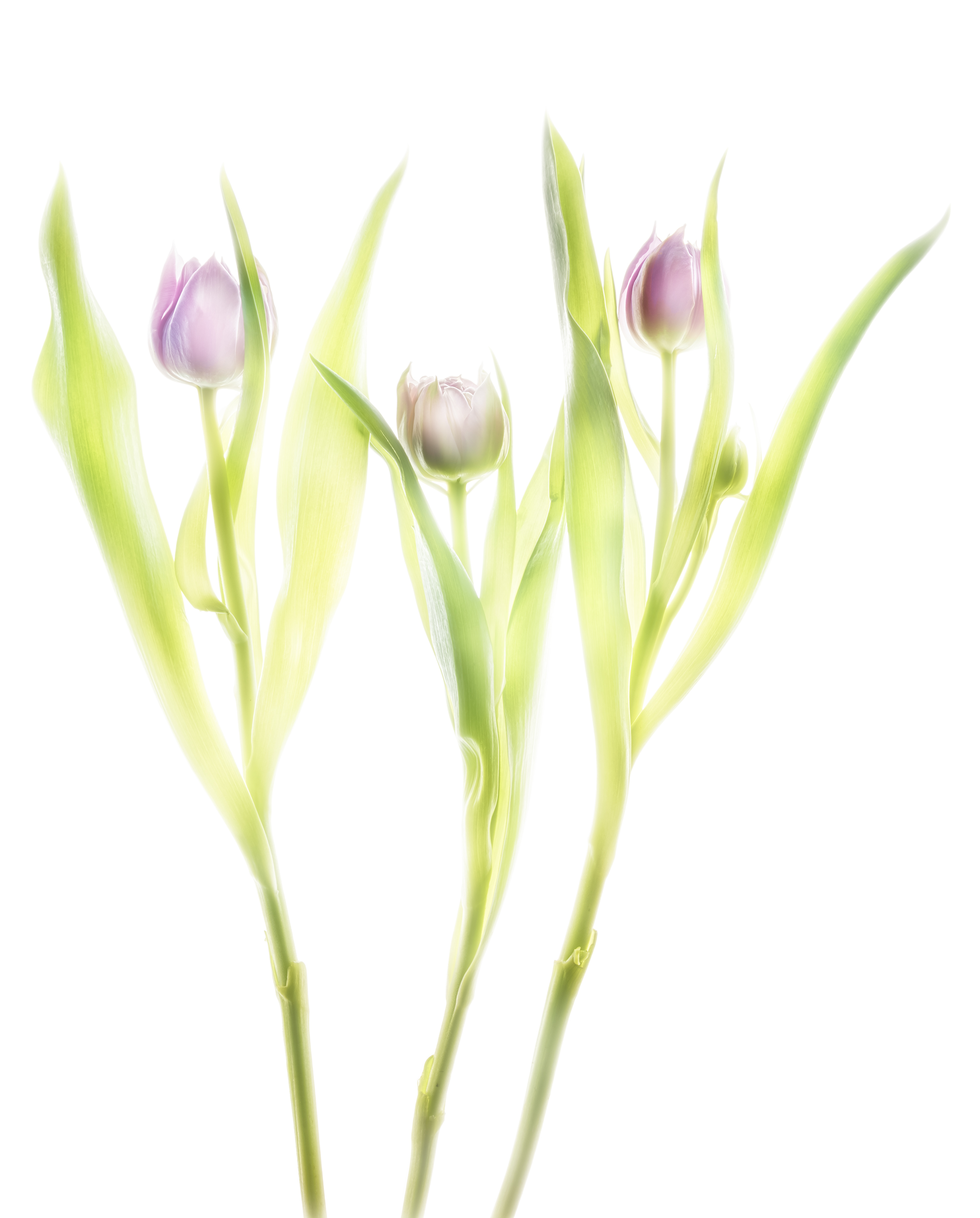
    Fusion X-ray of tulips

    Fusion imaging is beauty made of composite X-ray images and HDR images on a light box. The primary question is what energy fits best for flowers. To my experience 40 kV is often suitable. But: the proof of the pudding is in the eating.

    Mammography systems start e.g. from 20 kV and reach 39 kV. The sensor is up to 24cm x 30cm. Conventional systems start from 40 kV and reach 125 kV. The sensor is up to 43cm x 43cm what makes them more attractive to floral compositions.

    The higher resolution and the lower energies of a mammography will suit better for transparent objects. But the spatial limit of a composition (which is 24cm x 30cm) might put hard restrictions on the artist.

    Floral compositions have more creative space with a bigger sensor. But the X-ray tube starts with 40 kV and this might lead to overexposure of tender structures.

    Thus I performed today more than ten compositions to study this relation.

    After four exposure of three tulips I found this composition with four dense blossoms attractive to go further. The composition might somehow resemble to a sketch of three angels. The image is nice due to very soft edges of their „wings“, technically blown out portions in the image.  The inner structure of the nearly closed blossoms is well resolved. The stalks serve as „body“. There is no advantage with higher energies.

    X-ray three tulips © Julian Köpke

    The same composition was done immediately after the X-ray as a bracketing series on a lightbox. After returning I processed a manual HDR, the colors not to warm.

    Three purple tulips HDR photo © Julian Köpke

    The final fusion image is a composite of the preceding two images. Compared to the lightbox photo, the hidden stalks reappear naturally, the inner petals are outlined like a sketch.

    Three purple tulips fusion X-ray photo © Julian Köpke
  • X-Ray

    Radiating Beauty: Creating a new photographic form with fusion X-Ray images

    The shapes and forms are recognizable, yet the level of detail is deeper than the human eye can normally perceive: Leaves appear minutely laced and surfaces are impossibly intricate, somewhere between translucent and opaque. Welcome to the captivating work of photographer Harold Davis and radiologist Dr. Julian Köpke, who combine their skill, passion, and vision to create stunning X-ray photography and pioneering fusion images. Read more on the Pixsy blog (article by Natalie Holmes).

    This nice article was posted today to share the fascination of our common work on fusion X-ray images using a light box manual HDR photo of flowers and their X-ray.

    X-ray fusion image of a Gloriosa lilly © Julian Köpke

    Our X-ray data are the same, our photographic data a nearly the same: Harold used a Nikon D850 and I used a Nikon D810A, which is modified for astrophotography. Our common lens was a Zeiss Makro-Planar T* 2/50 ZF.2.

    We have some techniques and some principles in common, yet we are different individuals with different results. The next image is partly inspired by Harold’s version. Blue is the complementary color to yellow and fits nicely into the petals. The red color in the center is an image of the sun in monochromatic Hα light using a Fabry-Perot-Interferometer. So this image is a triple fusion image of three different light sources ! If you look closer at 2pm in the center, there are two sunspots.

    This sunflower is a composit of X-ray, monochromatic Hα light of the sun and a sunflower on a lightbox. © Julian Köpke
  • X-Ray

    Dahlias fusion X-ray HDR photo

    Long time ago my friend Harold and I did these X-rays in my practice. There was so much to do. Today was a chance to process the fusion images. Some details can be found in my FAQs.

    The manual HDR is already appealing to our eyes.

    Dahlias using manual HDR in visible light

    There is some charm in the X-ray image of the same composition. The hidden parts of the stalks can be clearly seen. 

    Five Dahlias X-ray photo © Julian Köpke

    The fusion image of this composition shows both color and hidden structures.

    Dahlias fusion digital X-ray with manual HDR photo in visible light

    Finished image with a background:

    Dahlias fusion digital X-ray and manual HDR photo with background © Julian Köpke
  • X-Ray

    Nautilus shells 3D X-ray photo

    How does an X-ray look like with a complete, unsplit specimen of a Nautilus shell ? Will X-rays go through the object ?

    My three Nautilus shells I bought in Crete are split specimens. The following approach will give an answer to the question. My composition of my shells is 3-dimensional and in nearly upright position. X-rays were then done with different directions of the radiation to study the effect.

    Positioning of the three Nautilus shells on the X-ray sensor © Julian Köpke
    Positioning of the three Nautilus shells on the X-ray sensor © Julian Köpke

    The first image was obtained with radiation coming from the top.  The native X-ray representation is with a black background. Historically this was a film negative. Radiologists speak of „transparent“ areas where a film is black. Consequently, white areas are called „opaque“.

    The result of radiation coming from the top and slightly tilted shells gives different insights of each shell. The composition looks like a complex mathematical surface or some flying insect. 

    Nautilus shell 3D Digital X-ray Photo © Julian Köpke

    The inverted (or „positive“) representation is weightless and our mind starts to produce lots of phantasies about the composition.

    Nautilus shell 3D Digital X-ray Photo inverted © Julian Köpke

    The effect of colorizing an X-ray is not only graphically. It looks more natural.

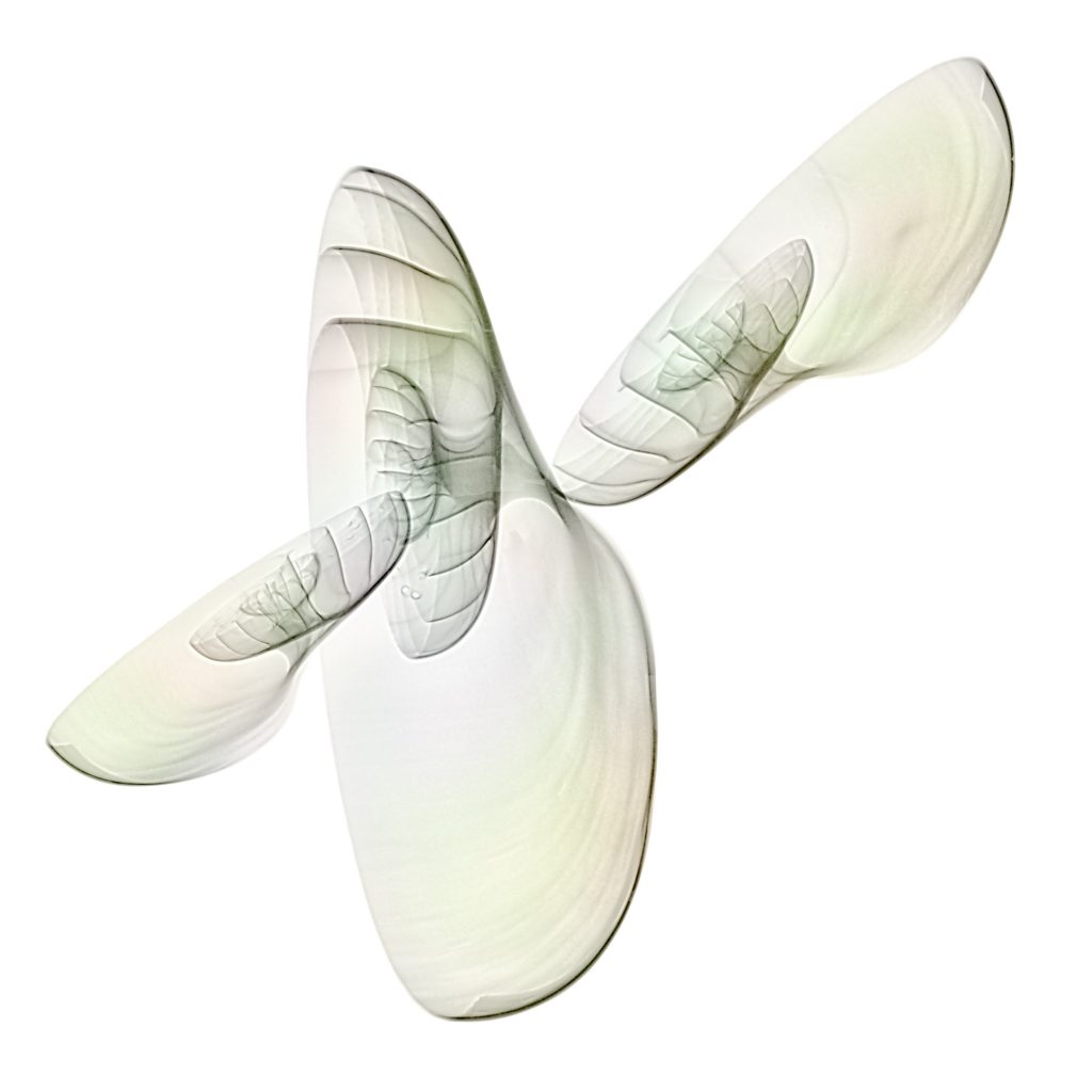
    Colorized Nautilus shell 3D Digital X-ray Photo © Julian Köpke

    The following image was obtained by combining the inverted image with a flat projection of a single shell to a single image. Now one gets an idea of the effect of the beam path.

    Nautilus shell 3D Digital X-ray Photo © Julian Köpke

    A tilted beam path shows the a bit more detail of the „wings“. Tilt was about 30 degrees.

    Nautilus shell 3D Digital X-ray Photo tilted beam © Julian Köpke
    Nautilus shell 3D Digital X-ray Photo tilted beam © Julian Köpke

    Tilt by 45 degrees shows more of a Nautilus as we know it.

    Nautilus shell 3D Digital X-ray Photo tilted beam © Julian Köpke